Fast, Accurate Power Converter Simulation
PLECS is a specialized power electronics simulation software that’s become the go-to tool for engineers designing converters, motor drives, and complex power systems. If you’re a power electronics engineer looking to streamline your simulation workflow or a student wanting to master industry-standard tools, this guide breaks down everything you need to know about PLECS.
This comprehensive guide is designed for power electronics engineers, graduate students, and researchers who work with converter simulation, motor drive simulation, and power system design. Whether you’re just starting with electronics simulation tools or want to maximize your existing PLECS workflow, you’ll find practical insights and real-world applications.
We’ll walk through PLECS fundamentals and show you how its unique architecture differs from other power electronics simulation software options. You’ll discover the core components and libraries that make PLECS powerful, from the PLECS blockset integration with MATLAB/Simulink to PLECS standalone capabilities. We’ll also cover advanced topics like real-time HIL simulation with the PLECS RT Box, plus practical tips for getting the most out of your PLECS student license if you’re in academia.
Understanding PLECS Fundamentals and Core Capabilities
What PLECS Software Offers Power Electronics Engineers
PLECS (Piecewise Linear Electrical Circuit Simulation) is a specialized simulation environment designed specifically for power electronics circuits and systems. Unlike general-purpose circuit simulators, PLECS focuses on the unique requirements of power electronic designs, providing engineers with tools that understand the behavior of switching converters, motor drives, and complex power systems.
The software comes in two main configurations: PLECS Standalone operates as an independent simulation environment with its own graphical interface, while PLECS Blockset integrates seamlessly with MATLAB/Simulink for engineers who prefer working within that ecosystem. Both versions share the same powerful simulation engine but offer different workflows depending on your preferred development environment.
Power electronics engineers benefit from PLECS’ ability to handle the fast switching behavior typical in converter circuits without getting bogged down in unnecessary detail. The software automatically manages the complex mathematical operations required for piecewise-linear analysis, allowing engineers to focus on circuit design rather than numerical methods.
For educational purposes, the PLECS Student License provides access to core functionality at an affordable price point, making it accessible for learning and academic projects. This version includes most essential features while maintaining compatibility with professional versions.
Key Features That Set PLECS Apart from Other Simulation Tools
PLECS distinguishes itself from traditional electronics simulation tools through several innovative approaches to power electronics modeling. The software’s piecewise-linear simulation method dramatically reduces computation time compared to SPICE-based simulators when analyzing switching circuits.
The thermal modeling capabilities stand out as particularly valuable for power electronics applications. PLECS includes built-in thermal networks that can be directly coupled to electrical components, enabling comprehensive analysis of heat generation and thermal management in power converters and motor drives.
Real-time HIL simulation capabilities through the PLECS RT Box enable hardware-in-the-loop testing, allowing engineers to validate control algorithms against actual hardware before full system integration. This real-time capability bridges the gap between simulation and physical testing.
Key differentiating features include:
Fast switching simulation: Optimized algorithms for rapid analysis of switching behavior
Integrated thermal modeling: Direct coupling between electrical and thermal domains
C-Script functionality: Custom component modeling using C-like syntax
Automatic code generation: Direct path from simulation to embedded code
Multi-domain modeling: Seamless integration of electrical, thermal, and mechanical domains
The software’s component libraries are specifically curated for power electronics, including detailed models of IGBTs, MOSFETs, diodes, and magnetic components that capture the essential behavior without unnecessary complexity.
Primary Applications in Power Electronics Design and Analysis
Power electronics simulation software like PLECS excels in several critical application areas where traditional simulation tools often fall short. The most common applications center around switching power supply design, where engineers can rapidly prototype and analyze different topologies before moving to hardware implementation.
Converter simulation represents one of PLECS’ strongest use cases. Whether designing DC-DC converters, AC-DC rectifiers, or DC-AC inverters, the software handles the switching behavior naturally while providing insights into efficiency, thermal performance, and control loop stability. Engineers can sweep design parameters, optimize component values, and predict performance across operating conditions.
Motor drive simulation applications benefit from PLECS’ ability to model both the power electronic converter and the motor as an integrated system. This includes analyzing the interaction between PWM switching patterns, motor harmonics, and overall system efficiency. The software can model various motor types including induction machines, permanent magnet synchronous motors, and brushless DC motors.
Primary application areas include:
- Renewable energy systems: Solar inverters, wind power converters, energy storage systems
- Electric vehicle powertrains: Onboard chargers, traction inverters, DC-DC converters
- Industrial motor drives: Variable frequency drives, servo amplifiers, motor control systems
- Power supplies: Switch-mode power supplies, LED drivers, battery chargers
- Grid-tied systems: Active power filters, power factor correction, grid inverters
The software’s strength in handling multiple time scales makes it particularly valuable for analyzing systems where fast switching events interact with slower thermal or mechanical dynamics, providing engineers with comprehensive insights into system behavior that would be difficult to obtain through hardware testing alone.
PLECS Architecture and Simulation Environment

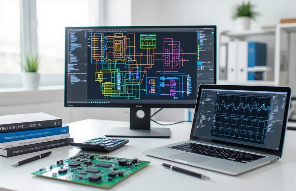
Circuit-Based Modeling Approach for Power Systems
PLECS takes a unique approach to power electronics simulation by focusing on circuit-level modeling that closely mirrors how engineers think about real systems. Unlike traditional simulation tools that rely heavily on mathematical abstractions, PLECS standalone and the PLECS blockset for MATLAB/Simulink build circuits using actual components like switches, diodes, inductors, and capacitors.
The software excels at handling switching behavior in power converters, which is often where other electronics simulation tools struggle. Each component model includes detailed electrical characteristics, switching losses, and parasitic elements. This granular approach means you can build everything from simple buck converters to complex multi-level inverters with confidence that the results reflect real-world performance.
Power electronics engineers particularly appreciate how PLECS handles discontinuous conduction modes, snubber circuits, and magnetic coupling between components. The tool automatically manages the mathematical complexity behind the scenes while presenting an intuitive drag-and-drop interface for circuit construction.
Thermal and Control System Integration Capabilities
Modern power electronics simulation software needs to handle more than just electrical behavior, and PLECS delivers comprehensive multi-domain modeling capabilities. The thermal modeling features let you analyze junction temperatures, heat sink performance, and thermal coupling between components mounted on the same PCB.
The control system integration stands out because it seamlessly connects with MATLAB/Simulink environments. You can implement complex control algorithms, digital signal processing functions, and communication protocols without switching between different software platforms. This integration proves invaluable for converter simulation and motor drive simulation projects where control complexity often determines system performance.
PLECS handles everything from simple PI controllers to advanced field-oriented control schemes. The software includes pre-built control blocks for common functions like PWM generation, Clarke and Park transforms, and PLL algorithms. Engineers can also import custom C-code blocks for proprietary control algorithms.
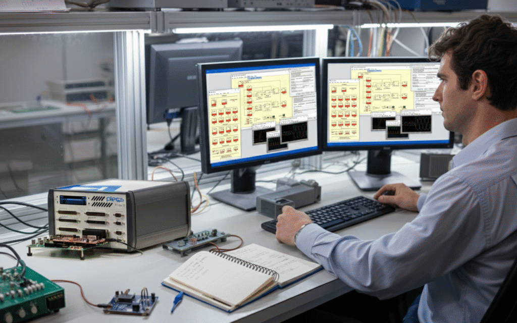
Real-Time Simulation Features for Hardware Testing
Real-time capabilities separate PLECS from many competing tools, especially when working with hardware-in-the-loop testing scenarios. The PLECS RT Box provides dedicated hardware for real-time HIL simulation, enabling engineers to test control hardware against virtual power systems running at microsecond time steps.
This real-time environment proves essential for validation testing before physical prototypes exist. Control boards can interface with the RT Box through standard I/O connections, experiencing the same electrical signals they would see in the final system. The real-time constraints force models to run efficiently, which actually improves simulation quality by eliminating unnecessarily complex mathematical formulations.
The RT Box supports sample rates up to 1 MHz for critical control loops while maintaining deterministic timing. Engineers can monitor and modify parameters during runtime, making it possible to perform extensive parameter sweeps and robustness testing without stopping the simulation.
User Interface Design for Efficient Workflow Management
PLECS prioritizes workflow efficiency through thoughtful interface design that reduces the time between concept and results. The schematic editor uses familiar electrical engineering symbols and conventions, making it intuitive for anyone with circuit design experience. Component libraries organize parts logically by function rather than mathematical complexity.
The PLECS student license provides full access to these interface features, making it an excellent choice for academic environments where learning curve considerations matter. Students can focus on understanding power electronics concepts rather than wrestling with software complexity.
Parameter management becomes straightforward through hierarchical organization and automatic unit handling. The software includes comprehensive plotting capabilities with customizable dashboards for monitoring multiple signals simultaneously. Batch simulation features enable design space exploration through automated parameter sweeps, while the integrated scripting environment allows for custom analysis routines and report generation.

Power Electronic Switches and Semiconductor Models
PLECS standalone and PLECS blockset come packed with comprehensive semiconductor models that cover the entire spectrum of power electronic switches. The software includes detailed models for MOSFETs, IGBTs, diodes, thyristors, and GTOs, each with configurable parameters for forward voltage drop, on-resistance, switching losses, and thermal characteristics.
The MOSFET models support both ideal and detailed representations. You can choose between simple switch models for rapid circuit analysis or detailed models that account for body diode characteristics, gate charge effects, and temperature dependencies. IGBT models feature separate modeling of the collector-emitter saturation voltage and tail current during turn-off, making them perfect for motor drive simulation scenarios.
Diode models range from basic ideal switches to sophisticated representations including reverse recovery characteristics and forward voltage temperature coefficients. For specialized applications, the software provides wide bandgap semiconductor models for SiC and GaN devices, capturing their unique switching characteristics and reduced switching losses.
Each semiconductor model allows you to input manufacturer datasheets directly, making real-world converter simulation more accurate. The thermal modeling capabilities let you connect thermal networks to monitor junction temperatures and implement thermal protection schemes.
Passive Components and Magnetic Elements
The passive component library in this electronics simulation tools suite provides extensive modeling options for capacitors, inductors, and resistors. Capacitor models include ideal linear types, electrolytic models with ESR and leakage current, and film capacitors with voltage-dependent characteristics.
Inductor modeling goes beyond basic L-R networks. The software includes saturable inductor models with configurable B-H curves, coupled inductors for transformer applications, and air-core inductors with frequency-dependent losses. For power electronics simulation software applications, the magnetic core models support various materials including ferrite, powder cores, and laminated steel.
Transformer models deserve special attention in PLECS. You can build transformers using coupled inductors with detailed leakage inductance modeling, or use the dedicated transformer blocks that automatically handle turns ratios and magnetizing inductance. The software supports both ideal transformers for quick analysis and detailed models that include core losses, saturation effects, and winding resistances.
Resistor models include temperature-dependent types and non-linear resistors for modeling varistors and thermistors. The component library also features specialized elements like RC snubbers, current sensors with bandwidth limitations, and voltage sensors with input impedance modeling.
Control Blocks and Signal Processing Tools
PLECS excels in control system implementation with its extensive library of signal processing blocks. The control blocks seamlessly integrate with power circuit simulations, making it ideal for real-time HIL simulation applications using the PLECS RT Box.
Standard control blocks include PID controllers with anti-windup, transfer function blocks supporting both continuous and discrete implementations, and various mathematical operations. The software provides specialized blocks for power electronics applications like three-phase transformations (abc to dq0), space vector modulation blocks, and phase-locked loops.
Signal generation capabilities include sinusoidal sources with harmonic distortion, triangular carriers for PWM generation, and random signal generators for noise analysis. The pulse generation blocks support various PWM techniques including sine-triangle PWM, space vector PWM, and hysteresis controllers.
Digital control implementation is straightforward with sample-and-hold blocks, quantizers, and delay elements. You can model ADC and DAC characteristics including resolution effects and conversion delays. For advanced applications, the software includes lookup tables with interpolation, state machines, and custom C-script blocks for implementing complex algorithms.
The signal routing capabilities allow complex control architectures with multiplexers, switches, and bus selectors. These tools make it easy to implement switching between different control modes or create fault-tolerant control systems.
Measurement and Analysis Components
Measurement blocks in PLECS provide comprehensive monitoring capabilities for both electrical and thermal quantities. Voltage and current probes offer various measurement options including RMS values, harmonic analysis, and power calculations. The probes can measure instantaneous values or provide filtered outputs for control applications.
Power measurement blocks calculate active, reactive, and apparent power with configurable averaging windows. These blocks are essential for efficiency analysis and power quality studies in converter simulation projects. The software includes specialized blocks for measuring total harmonic distortion (THD) and individual harmonic components.
For motor drive simulation applications, the measurement library includes torque and speed sensors with realistic dynamics and noise characteristics. Temperature sensors model thermal time constants and can trigger protection functions when limits are exceeded.
Scope blocks provide real-time visualization during simulation with multiple trace capabilities, zoom functions, and measurement cursors. The software supports both time-domain and frequency-domain analysis with built-in FFT capabilities. For students using a PLECS student license, these visualization tools are particularly valuable for understanding power electronics concepts.
The data export capabilities allow seamless integration with MATLAB for post-processing analysis. You can export simulation data in various formats and create custom analysis scripts. The software also supports automated parameter sweeps and Monte Carlo analysis for design optimization and sensitivity studies.
Advanced Modeling Techniques in PLECS
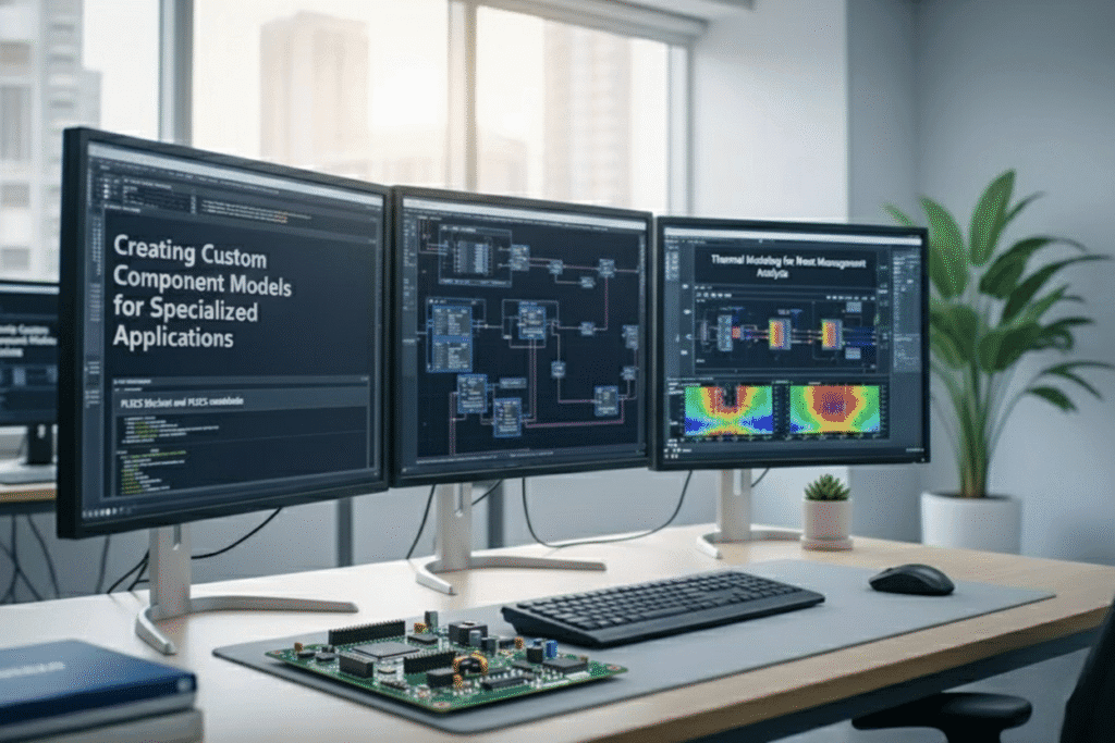
Creating Custom Component Models for Specialized Applications
PLECS provides powerful capabilities for developing custom component models when standard library components don’t meet specific simulation requirements. The PLECS blockset and PLECS standalone environments offer flexible modeling approaches through C-scripts, behavioral models, and user-defined blocks.
Custom component development typically starts with the C-script block, which allows implementation of complex mathematical relationships and control algorithms. These scripts can interface with external data files, perform real-time calculations, and handle variable initialization. For power electronics applications, custom models might include specialized gate drivers, protection circuits, or unique converter topologies not available in standard libraries.
The software supports both continuous and discrete modeling approaches. Continuous models work well for analog behaviors like non-linear magnetics or thermal effects, while discrete models handle digital control systems and communication protocols. Custom models can also incorporate look-up tables for efficiency maps, switching characteristics, or thermal properties.
Building reusable component libraries becomes essential for teams working on similar projects. PLECS allows packaging custom models into user libraries with proper documentation and parameter interfaces. This approach streamlines workflow and ensures consistency across different simulation projects.
Thermal Modeling for Heat Management Analysis
Thermal management represents a critical aspect of power electronics simulation software, and PLECS offers comprehensive thermal modeling capabilities. The software includes dedicated thermal blocks that model heat generation, conduction, convection, and radiation phenomena within power electronic systems.
The thermal modeling approach connects electrical power dissipation directly to temperature calculations. Semiconductor devices generate heat based on conduction and switching losses, which then affects junction temperatures. This temperature feedback influences device characteristics, creating realistic thermal-electrical coupling essential for accurate simulations.
PLECS thermal models support multiple heat transfer mechanisms. Thermal resistances and capacitances create RC networks that represent heat flow paths and thermal masses. These networks can model complex geometries including heat sinks, thermal interface materials, and PCB layouts. The software also handles forced convection scenarios with variable cooling conditions.
Advanced thermal modeling includes ambient temperature variations, thermal time constants, and temperature-dependent material properties. Users can implement thermal protection algorithms that respond to over-temperature conditions, simulating real-world safety mechanisms. This capability proves valuable for designing cooling systems and evaluating thermal stress in power converters.
Loss Calculation Methods for Efficiency Optimization
Accurate loss calculation forms the foundation of efficiency optimization in power electronics systems. PLECS implements sophisticated loss models that account for both conduction and switching losses across different semiconductor technologies including MOSFETs, IGBTs, and diodes.
Conduction loss models use device-specific on-state resistance characteristics that vary with temperature and current. The software interpolates from manufacturer datasheet curves or user-defined tables to calculate instantaneous power dissipation. Temperature coefficients ensure losses track junction temperature changes throughout simulation cycles.
Switching loss calculation methods include energy-based and behavioral approaches. Energy-based models use turn-on and turn-off energy curves from device datasheets, adjusted for actual switching conditions like current, voltage, and gate resistance. Behavioral models implement mathematical functions that represent switching transitions with adjustable parameters for rise/fall times and voltage/current overlaps.
PLECS also calculates magnetic component losses including core losses and copper losses in inductors and transformers. Core loss models implement Steinmetz equations with frequency and flux density dependencies. Copper losses account for DC resistance, skin effect, and proximity effect at higher frequencies.
Loss analysis reports provide detailed breakdowns showing where energy dissipation occurs within the system. These reports guide optimization efforts by identifying dominant loss mechanisms and comparing different design alternatives.
Scripting and Automation for Complex Simulations
Scripting capabilities in PLECS enable automation of complex simulation workflows, parameter sweeps, and batch processing tasks. The integrated scripting environment supports MATLAB-compatible syntax for users familiar with that environment, while also providing Python integration options.
Parameter variation studies become straightforward through scripting. Users can automate sweeps across multiple variables like switching frequency, load conditions, or component values. Scripts can modify circuit parameters, execute simulations, and collect results automatically. This automation proves invaluable for design optimization and sensitivity analysis.
Real-time HIL simulation scenarios benefit significantly from scripting automation. Scripts can coordinate test sequences, manage data logging, and interface with external hardware controllers. The PLECS RT Box leverages these capabilities for automated hardware-in-the-loop testing protocols.
Advanced scripting applications include Monte Carlo analysis for component tolerances, automated report generation with customized plots and tables, and integration with design databases. Scripts can also handle post-processing tasks like FFT analysis, harmonic distortion calculations, and efficiency mapping.
Batch simulation capabilities allow overnight processing of extensive parameter studies or design verification runs. Results can be automatically organized into databases or spreadsheet formats for further analysis. This automation significantly reduces manual simulation tasks and enables comprehensive design exploration that would be impractical with manual methods.
Practical Implementation Strategies
Setting Up Your First Power Electronics Circuit
Getting started with your first power electronics simulation in PLECS standalone or PLECS blockset doesn’t have to feel overwhelming. The key lies in breaking down your circuit into manageable blocks and understanding the signal flow from input to output.
Start by identifying the basic building blocks of your circuit: power sources, switching devices, passive components, and control systems. PLECS excels at handling these different domains through its intuitive drag-and-drop interface. Whether you’re designing a DC-DC converter or working on motor drive simulation, begin with the power stage first, then add your control logic.
The component library in PLECS provides pre-built models for common power electronics devices. For switching converters, you’ll typically start with:
- Voltage or current sources for your input
- IGBT, MOSFET, or diode models for switching elements
- Inductors and capacitors for energy storage
- Load resistors or motor models for your output stage
Connect these components using PLECS’ electrical connection lines, paying attention to proper grounding. The software automatically handles the electrical node connections, but you need to ensure your circuit topology makes physical sense.
For students working with a PLECS student license, the same principles apply, though you might encounter some component limitations. Don’t worry – the core functionality remains robust enough for most academic projects and learning exercises.
Simulation Parameter Configuration for Accurate Results
Proper parameter configuration makes the difference between meaningful results and frustrating simulation errors. The simulation settings window in PLECS controls everything from solver selection to output timing, and getting these right is crucial for electronics simulation tools to deliver accurate results.
Start with the simulation time settings. Set your stop time based on what you want to observe – transient startup behavior might need 50-100ms, while steady-state analysis could require several seconds. The step size determines simulation accuracy and speed. For switching converter simulation, use fixed-step solvers with step sizes around 1/20th of your switching period.
Solver selection depends on your circuit characteristics:
| Circuit Type | Recommended Solver | Typical Step Size |
|---|---|---|
| Hard-switched converters | Radau-IIa | 1/50 × Tsw |
| Resonant converters | Dormand–Prince | 1/100 × Tsw |
| Motor drives | Radau-IIa | 1/20 × Tsw |
| Linear circuits | Any | Larger steps OK |
The thermal simulation settings become important when dealing with semiconductor losses and thermal management. Enable thermal modeling for switching devices if you want to capture temperature effects on performance.
Initial conditions often get overlooked but can save significant simulation time. Set capacitor voltages and inductor currents to their expected steady-state values when possible. This prevents the long startup transients that add unnecessary computation time.
Post-Processing and Data Analysis Techniques
Raw simulation data tells only part of the story. PLECS provides powerful post-processing tools that transform your time-domain results into meaningful engineering insights. The built-in scope blocks capture waveforms during simulation, but the real magic happens in the analysis phase.
The FFT analysis tool helps you understand harmonic content in your switching waveforms. This proves especially valuable for power electronics simulation software applications where THD and spectral compliance matter. Access the FFT by right-clicking any scope trace and selecting “FFT Analysis” from the context menu.
For efficiency calculations, use the power probe components to measure instantaneous power flow. PLECS automatically calculates average values over specified time windows, making it easy to determine converter efficiency under different operating conditions. The probe placement strategy matters – measure input power before any control circuitry and output power at the actual load terminals.
Statistical analysis becomes crucial when evaluating switching losses or ripple performance. The scope’s statistics panel provides RMS values, peak-to-peak measurements, and average calculations. For switching loss analysis, combine current and voltage probes on your semiconductor devices with the multiplication block to get instantaneous power dissipation.
Export capabilities in PLECS allow you to move data into MATLAB, Excel, or other analysis tools for advanced processing. The “Export to Workspace” feature works seamlessly with MATLAB’s signal processing toolboxes when you need custom analysis beyond PLECS’ built-in capabilities.
Custom measurement circuits using voltage and current sensors can calculate complex parameters like power factor, displacement angle, or custom control metrics. These measurement blocks update in real-time during simulation, giving you immediate feedback on circuit performance changes.
Integration with Hardware and Other Software Tools
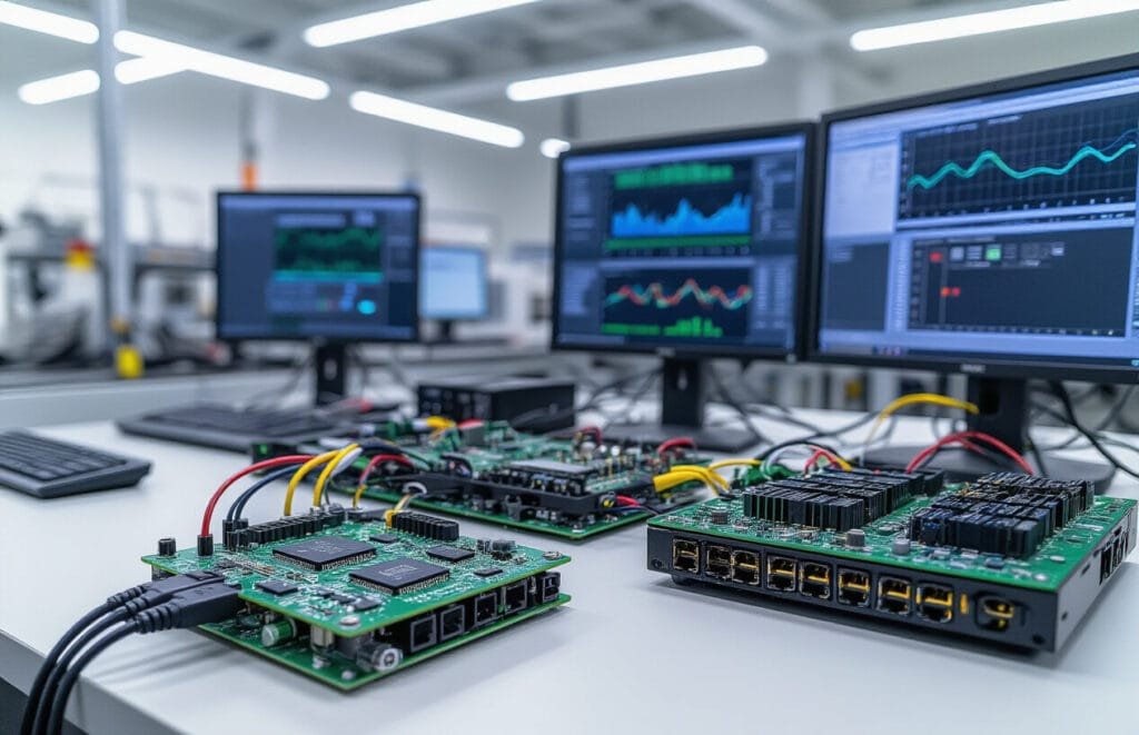
Hardware-in-the-Loop Testing Capabilities
PLECS brings your power electronics designs closer to real-world testing through its comprehensive hardware-in-the-loop (HIL) capabilities. The PLECS RT Box serves as the cornerstone for real-time HIL simulation, enabling engineers to test control algorithms and protection systems with actual hardware components before moving to expensive prototypes.
The RT Box connects seamlessly with your PLECS models, running simulations in real-time with microsecond-level precision. This approach lets you validate control strategies, test fault scenarios, and verify system behavior under various operating conditions without risking damage to expensive hardware. You can interface with actual inverters, motor drives, and control boards while the power stage remains safely simulated.
Key advantages include:
Real-time execution with deterministic timing
Analog and digital I/O for hardware interfacing
Built-in protection mechanisms for safe testing
Support for both converter simulation and motor drive simulation
Scalable from simple control loops to complex multi-megawatt systems
Code Generation for Real-Time Implementation
PLECS streamlines the transition from simulation to implementation through automated code generation capabilities. The software can export optimized C code directly from your simulation models, dramatically reducing development time and minimizing human error in the translation process.
The code generation process maintains the exact mathematical relationships established in your PLECS models while optimizing for target hardware constraints. Whether you’re targeting DSPs, FPGAs, or microcontrollers, PLECS adapts the generated code to match your platform’s specifications and performance requirements.
Generated code features include:
- Optimized algorithms for real-time execution
- Configurable sampling rates and execution priorities
- Built-in overflow protection and numerical stability
- Support for fixed-point and floating-point arithmetic
- Comprehensive documentation and variable mapping
Integration with MATLAB/Simulink and Other Platforms
PLECS offers flexible integration options that complement existing engineering workflows. The PLECS Blockset for MATLAB/Simulink allows engineers to incorporate PLECS circuit models directly into Simulink environments, combining the strengths of both platforms.
This integration proves particularly valuable when working with complex control systems that require MATLAB’s signal processing capabilities or Simulink’s extensive control system libraries. You can model the power electronic converter in PLECS while designing controllers, observers, and system-level behavior in Simulink.
The PLECS Standalone version provides independent operation while maintaining compatibility with various electronics simulation tools. Data exchange formats support seamless collaboration with other power electronics simulation software packages, ensuring your PLECS models integrate smoothly into broader design ecosystems.
Integration capabilities span:
- Bidirectional data exchange with MATLAB workspace
- Co-simulation with Simulink models
- Python scripting interface for automation
- CSV and Excel data import/export
- Third-party tool connectivity through APIs
Export Options for PCB Design and Manufacturing
PLECS bridges the gap between circuit simulation and physical implementation through comprehensive export options tailored for PCB design and manufacturing workflows. The software generates detailed component specifications, thermal requirements, and layout guidelines that PCB designers can directly incorporate into their designs.
Thermal analysis results export as detailed reports showing component stress levels, junction temperatures, and cooling requirements. This information guides PCB layout decisions, component selection, and thermal management strategies. Loss calculations translate into specific heat sink requirements and copper area recommendations.
The export functionality includes:
Bill of materials with precise component specifications
Thermal stress analysis and cooling requirements
Layout guidelines for high-power components
EMI considerations and filtering requirements
Manufacturing tolerances and testing parameters
Component libraries in PLECS maintain links to manufacturer part numbers and specifications, ensuring exported designs reference actual, purchasable components. This connection between simulation and reality reduces design iterations and improves first-pass success rates in PCB manufacturing.
Whether you’re designing simple DC-DC converters or complex three-phase systems, these export capabilities ensure your PLECS simulations translate effectively into manufacturable hardware solutions.
Performance Optimization and Best Practices
Simulation Speed Enhancement Techniques
Maximizing simulation performance in PLECS Standalone requires strategic optimization across multiple dimensions. The most effective approach involves reducing the computational burden through intelligent model design and solver configuration.
Start by examining your switching frequency and simulation step size relationship. Running simulations with unnecessarily small time steps dramatically increases computation time. Set your maximum step size to approximately 1/20th of your switching period for PWM-based systems. For converter simulation applications, this balance provides accurate results without excessive overhead.
Component selection plays a crucial role in performance. Replace detailed semiconductor models with simplified versions during initial design phases. The built-in PLECS components offer excellent speed-to-accuracy ratios for most power electronics simulation software applications. Reserve detailed models for final validation stages.
Solver selection significantly impacts speed. The auto-selected solver works well for most cases, but manual selection can yield better results. Fixed-step solvers typically run faster than variable-step solvers for power electronic circuits with known switching patterns. For motor drive simulation projects, consider using discrete solvers when continuous behavior isn’t critical.
Implement smart scoping strategies. Recording every signal creates massive data files and slows simulations. Focus on essential signals during development, then expand monitoring for specific analysis needs. Use triggered scoping to capture events rather than continuous recording.
Memory Management for Large-Scale Simulations
Large-scale simulations in PLECS Blockset and standalone versions demand careful memory planning to prevent crashes and maintain reasonable execution times. Understanding memory allocation patterns helps optimize complex power system models.
The primary memory consumers include signal history storage, large lookup tables, and extensive circuit matrices. Signal recording represents the biggest memory drain in most simulations. Each recorded signal consumes memory proportional to simulation time and sampling rate. Calculate expected memory usage: signal count × simulation time × sampling frequency × 8 bytes per sample.
For real-time HIL simulation applications, memory management becomes even more critical. The PLECS RT Box has finite memory resources that must accommodate the model, signal buffers, and real-time constraints. Implement circular buffers for signals that don’t require complete history preservation.
Optimize lookup table usage by reducing resolution where possible. High-resolution tables for motor characteristics or magnetic curves consume significant memory. Find the minimum resolution that maintains accuracy while reducing memory footprint. Consider using mathematical approximations instead of extensive lookup tables when practical.
Matrix sparsity optimization helps with large circuit networks. PLECS automatically handles matrix optimization, but model structure affects efficiency. Avoid unnecessary ideal switches and use realistic parasitic values to improve matrix conditioning.
Troubleshooting Common Modeling Issues
Power electronics models in PLECS encounter predictable issues that experienced engineers learn to identify and resolve quickly. Understanding these patterns accelerates development and improves model reliability.
Numerical oscillations frequently occur at switching instants, particularly in models with ideal switches and reactive components. Add small snubber circuits or realistic parasitic resistances to eliminate high-frequency oscillations. For electronics simulation tools, these parasitics actually improve model realism while solving numerical problems.
Algebraic loops present another common challenge, especially in control system designs with direct feedthrough paths. Break these loops using small delays or zero-order holds. The delay should be much smaller than the system time constants but large enough to prevent numerical issues.
Initial condition problems manifest as unexpected transients or convergence failures. Pay special attention to capacitor voltages and inductor currents at simulation start. Use steady-state initialization features in PLECS to automatically calculate appropriate initial conditions for periodic steady-state operation.
Control system integration issues often arise when mixing continuous and discrete control blocks. Maintain consistent sample rates throughout control paths and use proper anti-aliasing filters when interfacing with plant models. For PLECS Student License users learning these concepts, start with simple control structures before adding complexity.
Ground reference problems can cause convergence difficulties in complex circuits. Ensure proper electrical grounding in all circuit branches and avoid floating circuit sections. Use high-value resistors to ground when necessary for numerical stability.
Thermal modeling challenges require careful parameter estimation and reasonable thermal capacitances. Unrealistic thermal time constants can cause simulation instability or extremely slow convergence during thermal transients.
Conclusion
PLECS stands as a game-changing simulation platform that transforms how power electronics engineers approach circuit design and analysis. From its intuitive modeling environment to its extensive component libraries, PLECS offers the tools you need to tackle everything from basic converter designs to complex multi-domain systems. The platform’s ability to seamlessly integrate thermal, mechanical, and control elements makes it invaluable for today’s increasingly sophisticated power systems.
Getting started with PLECS means embracing a workflow that prioritizes both accuracy and efficiency. The software’s hardware integration capabilities and optimization features help bridge the gap between simulation and real-world implementation. Whether you’re validating a new converter topology or fine-tuning control algorithms, PLECS provides the foundation for confident engineering decisions. Start with the basics, explore the advanced features gradually, and watch your power electronics projects reach new levels of precision and reliability.