
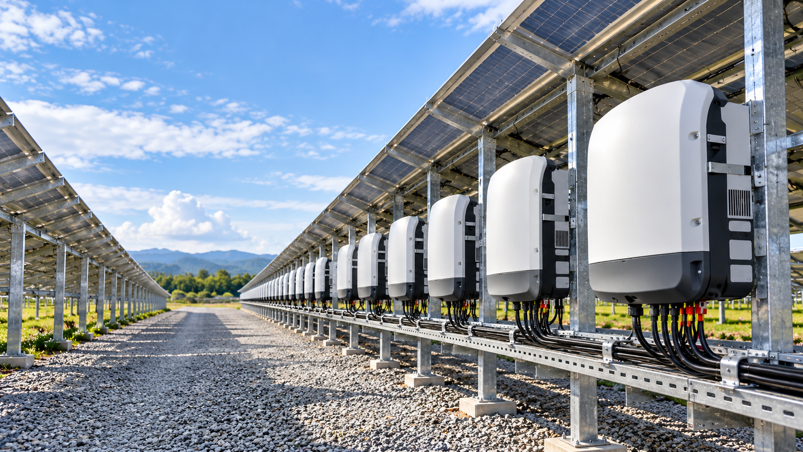
India’s installed solar capacity stood at about 171 GW at the end of September 2026, per MNRE data reported by trade media. Every gigawatt passes through an inverter, and its power semiconductor stage largely sets efficiency, heat and ageing. That makes choosing the right power modules for solar inverters one of the most consequential decisions in the design.
Quick answer
Power module selection matters because the module sets conduction and switching losses, junction temperature and thermal-cycling stress. A module that suits the topology, voltage class, switching frequency and cooling design can support efficiency and reliability. One chosen on current rating or price alone may run hotter and age faster.
India’s Solar Market and the Demand for Reliable Inverters
| Metric (installed capacity only) | Value | Basis |
|---|---|---|
| Installed solar, 30 Sep 2026 | ~171 GW | MNRE data, via Energetica India |
| Solar added, Jan–Sep 2026 | ~35.2 GW | JMK Research, via TaiyangNews |
| of which utility-scale / rooftop | ~24.4 GW / ~9.8 GW | JMK Research |
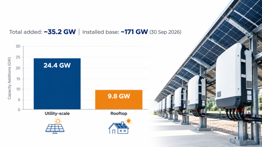
These figures exclude announced projects and targets. The design brief that follows is more power in less volume, outdoors, in heat and dust, with limited servicing. Sungrow runs an inverter factory near Bengaluru, reported at 10 GW annual capacity in 2022, and Hitachi Hi-Rel builds grid-tied solar inverters at Sanand, Gujarat. We have not verified which power modules either company uses.
What Causes Power Module Failures in Solar Inverters?
Direct answer
Mainly thermal-cycling fatigue, sustained high junction temperature, electrical overstress and weak cooling, sometimes compounded by gate-drive faults.
| Mechanism | What happens inside | Design response |
|---|---|---|
| Thermal cycling (bond-wire lift-off, solder fatigue) | Differing expansion rates crack interfaces. Thermal resistance rises, so the chip runs hotter. | Junction-temperature margin, mission-profile life estimate, robust die-attach and substrate |
| Excess junction temperature / poor cooling | Losses exceed heat removal, leading to derating or damage | Loss simulation at worst-case ambient, sound thermal interface, accessible heatsink cleaning |
| Electrical overstress | Overshoot from stray inductance plus DC-link transients exceeds rating | Low-inductance layout, voltage headroom, clamping where needed |
| Gate-drive faults | False turn-on, shoot-through or slow switching raises loss | Verified driver compatibility, dead-time, desaturation protection |
| Humidity / contamination | Leakage or corrosion, mostly at board and terminal level | Enclosure and coating design (largely system-level) |
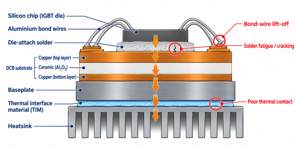
Aalborg University researchers describe bond-wire fatigue as one of the dominant IGBT failure mechanisms. But not every inverter failure starts in the module. Engineers quoted by pv magazine see IGBT faults less often than other problems, and chokes, boards and other parts also age.
Why Power Module Selection Matters for Solar Inverter Efficiency and Reliability
Key performance themes
- Conduction loss: set by VCE(sat) for IGBTs or RDS(on) for SiC MOSFETs at your real operating current.
- Switching loss: Eon and Eoff rise with frequency. Higher frequency can shrink magnetics but adds heat.
- Chip technology: Vincotech states that pairing Si IGBTs with SiC diodes removes reverse-recovery loss and lowers IGBT turn-on loss, and that SiC MOSFETs cut dynamic losses (Vincotech SiC power modules).
- Topology: three-level designs reduce the voltage each switch handles and the output ripple, at the cost of complexity.
- Packaging: low parasitic inductance and a good thermal path matter as much as the chip.
Comparing chip technologies for your next design? See our SiC power modules and IGBT power modules pages.
Direct answer
Vincotech’s solar inverter applications page lists Si, SiC and flying-capacitor topologies for inverters from 5 kW to 350 kW, with low parasitic inductance and robust die-attach as stated focuses.
Examples from its product listing:
| Segment | Topology | Example family (voltage / current / chip) |
|---|---|---|
| Residential | H6.5 | flowPACK 1 H6.5: 650 V, 100 A, IGBT S5 |
| Commercial & industrial | MNPC (T-type) | flowMNPC 0: 1200 V, 80 A, IGBT4 HS |
| 1500 V string | NPC / ANPC | flowNPC E3BP: 1200 V, 600 A, IGBT7 H7; flowANPC S3 split: 950 V, 600 A, IGBT S7 |
| 1500 V string, SiC | ANPC | flowANPC E3BP: 1200 V, 510 A, SiC MOSFET, 2.83 mΩ (samples available) |
| String boost stage | Flying capacitor | flowBOOST S3 triple: 950 V, 100 A, hybrid Si/SiC |
| Central | NPC / MNPC | VINcoNPC X12: 1200 V, 1200 A, IGBT M7 |
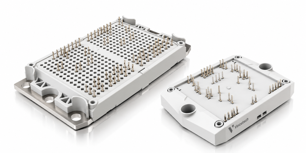
Product status varies between “Series” and “Samples available”, so confirm datasheet limits and availability before design-in. Vincotech also says its flying-capacitor topology avoids a large DC-link capacitor bank, and that its baseplated flow E3BP housing targets 350+ kW string inverters at 2000 V system requirements.
Define segment, power and DC voltage
- Single-phase up to about 10 kW → H6.5, optional integrated booster.
- Three-phase 5–200 kW → MNPC or NPC.
- 1500 V string → NPC, ANPC or flying-capacitor stages.
- Central, beyond 1000 VDC → low-inductance, high-current housings.
Match chip technology
Choose Si IGBT, hybrid Si/SiC or full SiC based on efficiency target, cooling budget, switching frequency and cost. Hybrid is common where cost matters, and Vincotech notes most SiC use today is in utility-scale string inverters and large storage.
Check voltage and current
- Compare maximum DC-link voltage, including transients, with the blocking voltage plus margin.
- In three-level NPC/ANPC each switch sees roughly half the DC link, which is why 950 V-class parts appear in 1500 V designs.
- Check peak current, including overload and grid-fault conditions.
Evaluate thermal performance
Calculate junction temperature at the worst-case site ambient and with a partly dusty heatsink:
Also check temperature swing (ΔTj), since it drives cycling fatigue.
Check switching frequency and gate drive
Read Eon/Eoff at your frequency and gate resistance, and confirm driver compatibility and protection.
Simulate and verify
Use Vincotech's VINcoSIM, which supports PLECS (see our PLECS guide), then confirm every figure against the datasheet.
What Should Solar Inverter Manufacturers in India Evaluate?
Conditions vary by site, so don’t assume one profile. Suppliers that publish derating data show 5–10% power loss at 50–55°C ambient versus 30°C. That puts junction-temperature margin and cooling design at the centre of module choice. Dust mostly becomes a maintenance task on fan-cooled or exposed heatsinks. Grid disturbances call for transient headroom, and poor service access raises lifecycle cost.
Building storage alongside PV? Many of the same topologies apply — see power modules for BESS.
Parameter Glossary
Tj / ΔTj
Junction temperature / its cycle swing
Rth(j-c)
Junction-to-case thermal resistance (K/W)
VCE(sat) / RDS(on)
On-state drop of an IGBT / on-resistance of a MOSFET
Eon / Eoff
Switching energy per event
NPC / MNPC / ANPC
Neutral-point-clamped / modified (T-type) / active NPC three-level topologies
Choosing power modules for solar inverters in India is a system decision. Match topology, chip technology and cooling to the site’s heat and service conditions, then verify against the datasheet.
Explore Vincotech Power Modules Through Pantronics India
Pantronics India lists Vincotech power modules (IGBT, MOSFET, SiC and hybrid) for solar, BESS, drives, EV charging and UPS. For a wider view of module types, see the Power Modules selection guide . When you contact us, share:
- Application and segment (residential, C&I, string, central)
- Power level, topology (if known) and switching frequency
- DC-link voltage range and AC grid voltage
- Ambient range and cooling method
- Volume and timeline
Frequently Asked Questions (FAQ)
No. SiC lowers dynamic losses but costs more. Hybrid Si/SiC is a common compromise in utility-string designs.
The sources reviewed don’t support that. Capacitors, fans, chokes and boards also age.
NPC, ANPC and flying-capacitor stages are the options Vincotech lists, with 950 V-class parts for three-level designs. Confirm limits in the datasheet.
Calculate Tj from losses and thermal resistance at worst-case ambient, then simulate at real operating points.
Application, voltage and current, topology, frequency, cooling and volume (see the list below).

Need help choosing the right power module for your inverter?
Talk to our technical team about topology, voltage class, IGBT vs SiC, switching losses and thermal margin for your solar inverter, BESS or drive application.
Mr. Vikrant Sharda (Power Module Expert)
Mail ID: v.sharda@pantronicsindia.com