
Power Modules Portfolio Overview
Power modules are integrated semiconductor assemblies that combine multiple active devices—diodes, thyristors, IGBTs, or MOSFETs—into a single packaged unit designed for efficient power conversion and control. Unlike discrete components, power modules simplify circuit design, reduce assembly complexity, and improve thermal performance through optimized internal layouts and integrated baseplates.
In India’s growing power electronics landscape, engineers rely on power modules for demanding applications across electric vehicle charging systems, solar inverters, UPS systems, industrial motor drives, induction heating equipment, welding machines, and HVAC controls.
This guide covers the complete Littelfuse (IXYS) power module portfolio available through Pantronics India Pvt. Ltd., the authorized distributor in India. We explain each subcategory—from AC bridge rectifiers to H-Bridge IGBT modules—with technical selection criteria, application contexts, and practical design considerations.
Power Modules Portfolio Overview
Littelfuse produces power modules under the legacy IXYS brand, combining diodes, thyristors, IGBTs, and MOSFETs into robust, thermally efficient packages. The portfolio addresses rectification, inversion, chopping, and switching across voltage classes from 40 V to 24 kV and current ratings from sub-ampere to over 1 kA.
Key Performance Themes
- Low Thermal Impedance: DCB substrates and optimized die attach reduce Rth(j-c), enabling higher current density and smaller heatsinks (0.03–1 K/W typical).
- High Overload Capacity: Peak surge currents (IFSM/ITSM) significantly higher than continuous ratings — e.g., a 700 A diode module handles 20 kA surge.
- Low Forward Voltage Drop: Alloyed die construction minimizes conduction losses. Typical VF: 1.0–2.5 V (diodes), VCE(sat): 1.7–2.0 V (IGBTs).
- Pressure Contact Mounting: Bolt-down designs with full baseplate contact ensure consistent thermal coupling.
- Isolation Voltage: 2.5–4.8 kVrms between junctions and baseplate for safe grounded mounting.
| Subcategory | What It Does | Typical Applications | Key Selection Parameters |
|---|---|---|---|
| AC Bridge Rectifiers | Convert AC mains to DC using diode, thyristor, or MOSFET bridges | Power supplies, battery chargers, DC motor drives, welding machines | VRRM, IFAV, surge rating, thermal impedance, package type |
| Diode Modules | Rectify AC to DC; building blocks for custom bridges | Rectifiers for PWM inverters, DC power supplies | VRRM (800 V–3.4 kV), IFAV, IFSM, Rth(j-c) |
| IGBT Modules | High-speed switching for medium/high power with low saturation | Solar inverters, UPS, EV chargers, motor drives, welding | VCE(sat), IC at 80°C, Eoff, gate charge, Rth(j-c) |
| MOSFET Modules | Ultra-fast switching with low Rds(on) for high-frequency converters | EV traction inverters, DC-DC converters, resonant power supplies | VDS, ID, Rds(on), dv/dt ruggedness, switching times |
| Thyristor Diode Modules | Solid-state rectifiers and switches for high-current AC systems | AC motor soft starters, DC motor controllers, lighting dimming | VRRM (up to 2.2 kV), IFAV, dv/dt rating, gate trigger |
| Thyristor Modules | Bidirectional AC power control using SCRs or TRIACs | Heating elements, tankless water heaters, phase control, AC motor control | VDRM, IT(RMS), ITSM, dv/dt, gate sensitivity |
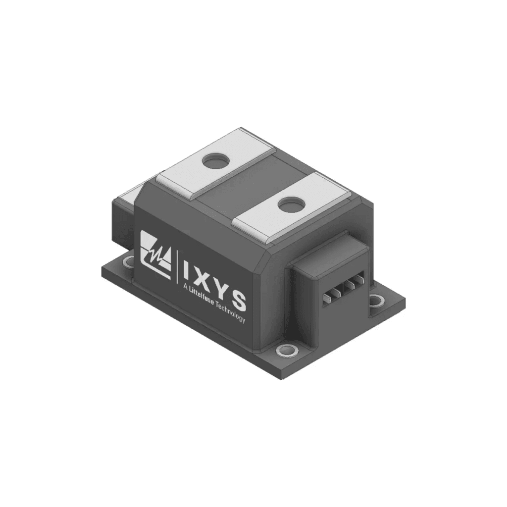
High-Voltage Rectifiers
Handle AC inputs up to 24 kV for specialized industrial and scientific equipment. VRRM ranges from 3.2 kV to 24 kV, with IFAVG from 1 A to 23 A. Applications include electron beam welders, industrial lasers, and X-ray generators.
Single-Phase Bridges
Use four diodes in a full-wave configuration to convert 230 V AC into pulsating DC. Key selection: VRRM ≥400 V for 230 VAC, IFAV rated for continuous load plus ripple margin, and IFSM to handle capacitor inrush.
Three-Phase Bridges
Six diodes convert three-phase AC to DC with less ripple (300 Hz at 50 Hz) than single-phase. Standard in VFDs, UPS DC bus supplies, and EV fast-charging stations. Choose VRRM ≥800 V for 415 VAC systems

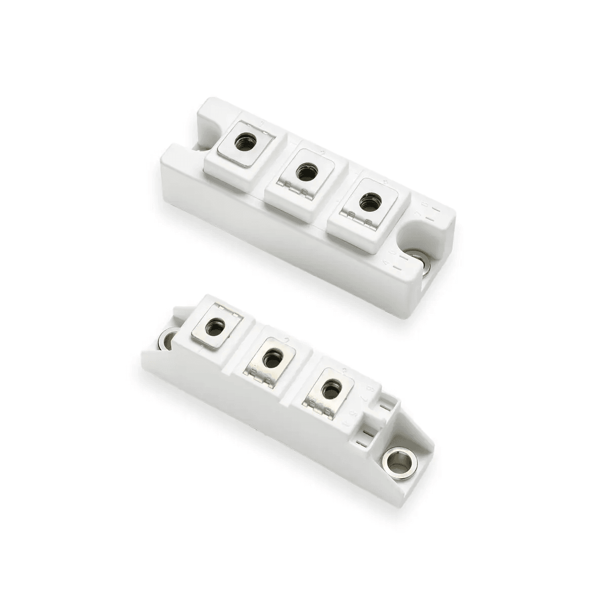
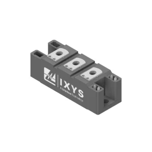
Single or dual diode assemblies in thermally optimized packages serve as building blocks for rectification, freewheeling, or snubber functions. Compared to discretes, modules provide lower thermal impedance, higher surge capability, and simplified heatsink attachment.
Dual Diodes
Two independent diode chips on a common baseplate. VRRM: 800 V–3.4 kV, IFAV: 35–700 A, IFSM: 600 A–20 kA. Used in half-bridge rectifiers, freewheeling applications, and center-tapped transformer rectification.
Single Diodes
One high-current diode chip. VRRM: 1.2–2.2 kV, IFAV: 35–700 A, IFSM: 15 kA. Used in DC motor drives, high-power rectification, and boost diodes in PFC stages

IGBTs combine the voltage-controlled gate of a MOSFET with low on-state voltage of a BJT. They offer lower conduction loss than MOSFETs at voltages above 600 V and current above 50 A, while switching faster than thyristors or BJTs.
Key Performance Characteristics
- VCE(sat): 1.7–2.0 V at rated current, determining conduction loss
- Eoff: Turn-off energy per pulse — lower Eoff enables higher switching frequency
- Gate Charge (Qg): Low Qg reduces gate driver power and improves efficiency
- Diode Recovery: Fast/soft recovery diodes minimize reverse recovery loss and EMI
Boost Choppers
Step up DC voltage through inductor-based energy transfer. VCE: 1.2–1.7 kV, IC at 80°C: 23–400 A. Used in PFC circuits, solar inverter boost stages, UPS systems, and regenerative braking in EVs.
Buck Choppers
Step down DC voltage by controlling duty cycle. VCE: 1.2 kV, IC at 80°C: 60–175 A. Feature SONIC™ fast and soft recovery diodes. Used in SMPS, switched reluctance motor drives, and battery charging circuits.
Buck-Boost Choppers
Bidirectional voltage conversion in a single module. Used in wide-input SMPS, battery management systems, switched reluctance drives, and DC microgrid voltage regulation.
Converter-Brake-Inverter (CBI)
Integrates AC-DC converter, brake chopper, and DC-AC inverter in one package. Reduces component count in VFDs for pumps, fans, compressors, and elevator/crane controllers with regenerative braking.
H-Bridge
Four IGBTs and four freewheeling diodes for bidirectional current flow. VCE: 1.2 kV, short-circuit rated for 10 μs. Used in DC motor controllers, single-phase UPS inverters, welding machines, and residential solar inverters.
MOSFETs offer lower switching loss than IGBTs above 50 kHz and below 600 V. Standard choice for EV traction inverters (48 V systems), DC-DC converters in telecom and automotive, synchronous rectification, and high-frequency resonant converters.
Key Performance Characteristics
- Rds(on): 1–25 mΩ, determining conduction loss
- Gate Charge (Qg): Lower Qg enables faster switching and reduces driver loss
- dv/dt Ruggedness: Withstands high voltage slew rates without false turn-on
- Switching Times: Rise/fall times of 50–110 ns
Configurations Available
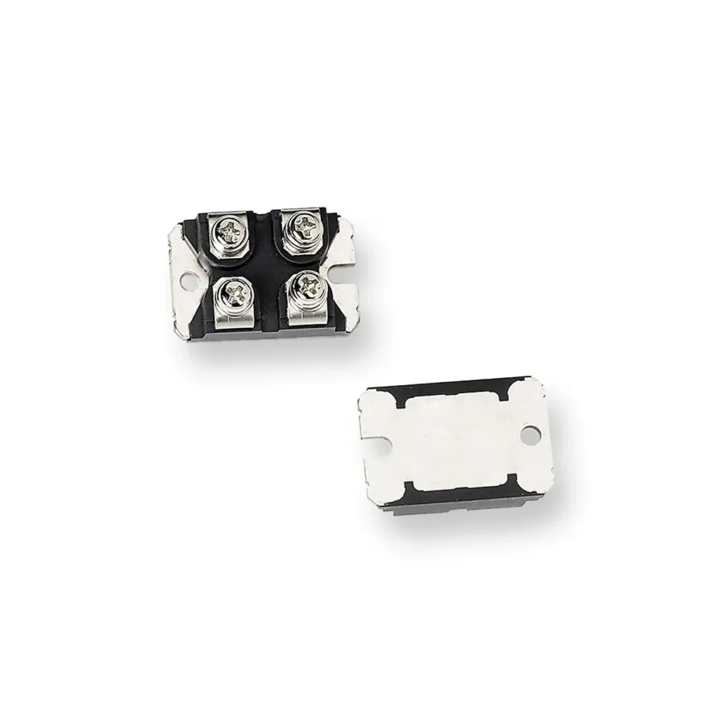
- Single Switch: One MOSFET + diode for DC-DC choppers (VDS: 100–500 V, Rds(on): 1.35–3.80 mΩ)
- Single Phase: Two MOSFETs forming one inverter phase leg
- Three-Phase Bridge: Six MOSFETs (VDS: 40–150 V, Rds(on): 1.1–24 mΩ) for motor drives and EV traction
- Trench MOSFET: Ultra-low Rds(on) for minimizing conduction loss in 48 V/100 V systems
Combine thyristors (SCRs) with diodes for phase-controlled rectification, motor soft starting, and controlled DC power. VRRM up to 2.2 kV. Used in AC motor soft starters, DC motor controllers, lighting controllers, and high-current battery chargers.
SCRs or TRIACs for bidirectional AC power control without integrated diodes. Key themes include phase control, zero-crossing switching, and bidirectional control with low on-state drop (1.5–2 V).
AC Switches / TRIACs
Three-terminal AC switches conducting in both directions. VDRM: 200 V–1.2 kV, IT(RMS): 800 mA–88 A. Used in heating control, lighting dimming, major appliances, and industrial power tools.
Dual Thyristors
Two independent SCRs on a common baseplate. VRRM: 800 V–2.4 kV, IFAV: 18–700 A, IFSM: 300 A–19 kA. Used in AC motor soft starters, DC motor controllers, and phase-controlled power converters.
Single Thyristors
One high-current SCR. VRRM: 1.2–2.2 kV, IFAV: 130 A–1.1 kA, IFSM: 3.6–30 kA. Used in line rectifiers, soft start circuits, and high-power DC motor drives.
Selection Guide: Engineer-Friendly Decision Flow
Step 1: Define Power Conversion Function
- Single-phase AC input → Single-Phase Bridge Rectifier
- Three-phase AC input → Three-Phase Bridge Rectifier
- High voltage (>1 kV) AC → High-Voltage Rectifier Module
- Phase control (variable DC) → Thyristor Diode or Thyristor Module
- Medium/high power (>1 kW), voltage >600 V → IGBT Module
- High-frequency (>50 kHz), low voltage (<600 V) → MOSFET Module
- AC power control → Thyristor Module (TRIAC or SCR)
Step 2: Match Semiconductor Technology
| Parameter | MOSFET | IGBT | Thyristor | Diode |
|---|---|---|---|---|
| Best Voltage Range | <600 V | 600 V – 3.3 kV | 600 V – 6 kV | 400 V – 24 kV |
| Best Current Range | <500 A | 10 A – 2 kA | 50 A – 3 kA | 1 A – 2 kA |
| Switching Speed | Very fast (ns) | Fast (µs) | Slow (line freq) | N/A |
| Conduction Loss | Rds(on) × ID² | VCE(sat) × IC | VT × IT | VF × IF |
| Switching Loss | Low | Moderate | N/A | Recovery loss only |
| Typical Application | DC-DC, low-V motor drives | Inverters, UPS, solar, welding | Soft starters, phase control | Rectification, freewheeling |
Step 3: Determine Voltage and Current Ratings
- MOSFET (VDS): 1.5× maximum DC bus voltage
- IGBT (VCE): 1.2–1.3× maximum DC bus voltage
- Diode/Thyristor (VRRM): 1.2–1.5× peak AC line voltage
- Derating: Continuous operation −10–20%, high ambient use junction temp at 125°C+, altitude >1000 m reduce current 5% per 1000 m
Step 4: Evaluate Thermal Performance
Calculate junction temperature: Tj = Ta + (Pcon + Psw) × (Rth(j-c) + Rth(c-h) + Rth(h-a)). Keep Tj below 100°C for continuous industrial operation. Use thermal paste with conductivity >3 W/mK and verify heatsink flatness (<50 μm deviation).
Step 5: Check Switching Frequency
- Diode/Thyristor: Line frequency to <1 kHz
- IGBT: 1 kHz to 50 kHz (trench up to 100 kHz)
- MOSFET: 50 kHz to 1 MHz
Pantronics India Pvt. Ltd. is an authorized distributor of Littelfuse power semiconductors in India, offering direct access to the complete IXYS power module portfolio with technical support, availability planning, and competitive pricing.
- Selection Support: Application engineers help with IGBT vs. MOSFET trade-offs, voltage/current class selection, and thermal performance evaluation
- Stock Availability: Common modules stocked in India, reducing lead-times from weeks to days
- Technical Documentation: Datasheets, thermal models, gate driver reference designs, and layout guidelines
- Sampling & Prototyping: Expedited samples for proof-of-concept validation
- Quality Assurance: All modules RoHS compliant, ISO quality standards, global warranty
- Local Presence: Understanding of BIS standards, import duties, GST, and Indian payment terms
Parameter Glossary
- VRRM / VDRM: Maximum repetitive reverse/blocking voltage
- VDS / VCE: Drain-source (MOSFET) / Collector-emitter (IGBT) voltage
- IFAV / IT(RMS): Average forward / RMS current rating
- IFSM / ITSM: Peak one-cycle surge current (non-repetitive)
- VF: Forward voltage drop at rated current
- VCE(sat): IGBT saturation voltage at rated current
- Rds(on): MOSFET on-state resistance
- Qg: Total gate charge
- Eon / Eoff: Turn-on / turn-off energy per switching cycle
- trr / Qrr: Diode reverse recovery time and charge
- dv/dt: Voltage slew rate (V/μs)
- Rth(j-c): Junction-to-case thermal resistance (K/W)
Conclusion and Next Steps
Power modules are the functional core of modern power conversion systems, determining efficiency, thermal performance, and reliability across applications from rooftop solar inverters to industrial motor drives.
Understanding the technical distinctions between diode, thyristor, IGBT, and MOSFET modules—and their subcategories—enables engineers to select the optimal semiconductor technology for any power conversion challenge.
Contact Pantronics India for selection support, sampling, and competitive pricing on the complete Littelfuse (IXYS) power module portfoli
Frequently Asked Questions
Power modules integrate multiple semiconductor devices (diodes, thyristors, IGBTs, MOSFETs) into a single package designed for power conversion and control. They are used in rectification (AC to DC), inversion (DC to AC), DC-DC conversion, AC switching, and motor drives. Applications include solar inverters, EV chargers, UPS systems, industrial motor drives, welding machines, and heating controls.
Choose IGBT modules when operating voltage is >600 V, switching frequency is <50 kHz, and power level is >1 kW — ideal for solar inverters, motor drives, UPS, and welding. Choose MOSFET modules when operating voltage is <600 V, switching frequency is >50 kHz, and low conduction loss is a priority — ideal for EV traction inverters (48 V), DC-DC converters, and synchronous rectification.
Single-phase bridges convert 230 V AC to DC using four diodes with 100 Hz ripple, requiring larger capacitors — used for <10 kW applications. Three-phase bridges convert 415 V AC using six diodes with 300 Hz ripple, reducing capacitor size — used for industrial motor drives, UPS systems, and high-power chargers (>10 kW) with lower input current harmonics.
dv/dt ruggedness is a MOSFET’s or thyristor’s ability to withstand high voltage slew rates (V/μs) without false turn-on or avalanche breakdown. It matters in hard-switching topologies with inductive loads where voltage spikes occur during turn-off, and in thyristor circuits where fast voltage transients can cause unintended triggering.
Thyristor diode modules enable phase-controlled rectification in AC motor soft starters. By delaying the gate trigger pulse relative to AC zero-crossing, they reduce applied voltage during motor startup, limiting inrush current and mechanical stress. Typical startup ramp is 5–20 seconds, gradually increasing voltage from 30% to 100%.
Share application type, input voltage (AC/DC, single/three-phase), output voltage and current, switching frequency, topology (if known), thermal constraints (ambient temperature, cooling method), special requirements (isolation, surge, certifications), and volume/timeline information.

Expert Technical Support
Looking For Littelfuse Power Modules In India? Pantronics India Offers Expert Support For AC Bridge Rectifiers, Diode Modules, IGBT Modules, MOSFET Modules, Thyristor Diode Modules, And Thyristor Modules With Strong Application Support For EV, Renewable Energy, UPS, And Industrial Power Systems.
Ms. Vikrant Sharda
(Specialized in Power Semiconductors & Circuit Protection)
Mail ID: v.sharda@pantronicsindia.com