Solving timing jitter, PWM synchronization errors, and protection delays in EV traction inverters, motor drives, and grid-connected converters.
Why Real-Time Deterministic Control Is Mission-Critical in Modern Power Electronics
In a 400V electric vehicle (EV) traction inverter operating at 20 kHz switching frequency, a timing jitter of just 500 nanoseconds can cause 3-5% torque ripple and audible whine. Yet traditional DSP (digital signal processor) and MCU (microcontroller unit) based controllers routinely introduce jitter of 1-10 microseconds—far beyond acceptable margins for high-performance systems.
This is the real-time control crisis facing modern power electronics engineers.
With the explosive growth of wide bandgap semiconductors like silicon carbide (SiC) and gallium nitride (GaN), switching frequencies in power converters are climbing from 10 kHz to beyond 100 kHz. Applications such as:
- EV traction inverters (permanent magnet synchronous motor control)
- High-speed electric motor drives (field-oriented control, direct torque control)
- Grid-connected converters (active front end, bidirectional power flow)
- Battery management systems (BMS) and onboard chargers (OBC)
- Renewable energy inverters (solar PV, wind power conditioning)
- Advanced research platforms (modular multilevel converters, multi-level topologies)
…are pushing the boundaries of what control systems can achieve. Control bandwidths are shrinking, closed-loop current control must respond within microseconds, and protection margins are tightening.
In this demanding environment, “Real-Time Control” means more than fast software execution—it requires deterministic execution. Control loops must fire at precisely scheduled intervals. PWM (pulse width modulation) edges must align with nanosecond accuracy. Over-current and over-voltage protection logic must react within sub-microsecond timeframes.
Traditional controllers—DSPs, MCUs, and PLC-based systems—were not architected for this level of precision. They rely on:
- Interrupt-based execution (with variable latency)
- Shared computational resources (CPU, memory bus contention)
- Software-managed timing (scheduler jitter, cache misses, pipeline stalls)
These architectural constraints introduce latency, jitter, and non-determinism into control loops—exactly what high-performance power electronics cannot tolerate.
Imperix has solved this challenge with purpose-built FPGA (field-programmable gate array) platforms engineered specifically for real-time control of power electronics. By implementing time-critical functions in dedicated hardware logic rather than sequential software, Imperix controllers deliver:
✅ Deterministic execution (zero timing jitter)
✅ Precise PWM generation (±2.0 ns synchronization accuracy)
✅ Sub-microsecond protection response (<1 μs fault reaction)
✅ Parallel processing (control and I/O execute simultaneously)
The Five Critical Real-Time Control Challenges in Power Electronics
1. Timing Jitter and Non-Deterministic Execution
In DSP and MCU-based systems, control execution timing depends on:
- Interrupt priority schemes (higher-priority tasks can preempt control loops)
- Background tasks (communication stacks, data logging, user interface)
- Cache behavior (cache misses add unpredictable delays)
- Pipeline stalls (branch mispredictions, memory access conflicts)
Even small execution delays—on the order of 1-5 microseconds—can destabilize fast current control loops in motor drives. Consider a 10 kHz control loop with a 100 μs period: even 2 μs of jitter represents 2% timing uncertainty.
Consequences of timing jitter:
- Instability in closed-loop current control
- Increased torque ripple in motor drives
- Total harmonic distortion (THD) degradation in grid inverters
- Reduced power factor correction (PFC) performance
- Unpredictable behavior during testing (results not reproducible)
The worst part? These issues rarely appear in offline simulation. They only manifest during hardware-in-the-loop (HIL) testing or on the actual power converter—when it’s expensive to fix.
2. PWM Synchronization Errors and Dead-Time Inconsistencies
PWM generation is the fundamental output of any power converter controller. In DSP and MCU-based systems, PWM update timing can suffer from:
- Late PWM updates (computation finishes after the PWM timer period starts)
- Phase misalignment between channels (multi-phase inverters lose synchronization)
- Inconsistent dead-time insertion (leading to shoot-through risk or excessive switching loss)
- Non-deterministic duty cycle application (command issued at t₀ but applied at t₀ + Δt)
When switching at 50 kHz or higher with SiC MOSFETs or GaN HEMTs, even 50 nanoseconds of PWM edge uncertainty can:
- Increase switching losses by 5-10%
- Generate EMI (electromagnetic interference) that fails compliance testing
- Cause distortion in space vector modulation (SVM) patterns
- Create audible noise in motor drive applications
Hardware abstraction layers (HALs) and timer peripherals in standard MCUs simply cannot guarantee the nanosecond-level precision required for modern wide bandgap power electronics.
3. Delayed Protection Response (Over-Current, Over-Voltage, Desaturation)
Protection mechanisms safeguard expensive power semiconductors (IGBTs, SiC MOSFETs, GaN devices) from catastrophic failure. In high-voltage, high-current converters, the energy stored in stray inductance and DC-link capacitors can destroy devices in microseconds.
Software-based protection paths typically experience:
- Polling delays (waiting for the next ADC sample or interrupt)
- Interrupt latency (5-20 μs on loaded CPUs)
- Context switching overhead (saving/restoring CPU state)
- CPU load dependency (protection response slows when CPU is busy)
Example scenario: A 800V EV inverter experiences an IGBT desaturation event. If the controller takes 10 microseconds to shut down PWM, the device can fail. With FPGA-based hardware protection reacting in <1 microsecond, the system shuts down safely.
This difference between safe operation and smoking hardware makes deterministic protection non-negotiable for:
- High-power industrial motor drives
- EV charging infrastructure (V2G bidirectional chargers)
- Grid-scale energy storage systems
- Traction inverters in electric vehicles (meeting ISO 26262 safety standards)
4. Signal Disablement and Enable Timing Inconsistencies
When shutting down or restarting a multi-phase power converter, all PWM channels must disable (or re-enable) simultaneously and repeatably. In software-controlled systems:
- Signal disablement propagates sequentially through I/O registers
- Channel-to-channel skew can reach hundreds of nanoseconds
- Timing varies with CPU load, interrupt status, and software state
Consequences:
- Asymmetric stress on power devices during emergency shutdown
- DC bias injection into transformer-coupled converters
- Unpredictable startup transients in motor drives
- Difficulty meeting automotive SPICE and IEC 61850 timing requirements
Multi-level converters (neutral-point clamped, flying capacitor, modular multilevel) are especially sensitive to these issues, as voltage balancing depends on perfectly synchronized switching.
5. High-Speed I/O Bottlenecks in Multi-Channel Systems
Modern power electronics systems demand:
- 16-24 PWM output channels (multi-motor drives, MMC converters)
- 12-16 high-speed ADC inputs (phase currents, DC-link voltage, temperature)
- Encoder interfaces (resolvers, incremental/absolute encoders for motor position)
- Fast ADC triggering (synchronized with PWM for accurate current sampling)
- Digital I/O (fault signals, enable/disable, status indicators)
In MCU and DSP-based systems, these I/O operations compete for CPU cycles. The more complex the system, the harder it becomes to maintain deterministic timing. Communication tasks (CAN, Ethernet, USB) further steal CPU resources from real-time control.
Result: Engineers must compromise between system complexity and control performance.
How Imperix Delivers Deterministic Real-Time Control
Imperix has architected its controller platforms around a core principle: implement time-sensitive control and protection functions directly in FPGA hardware, not in sequential software. This eliminates the root causes of jitter and latency.
Hardware-Based PWM Generation and High-Speed I/O
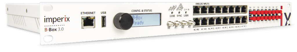
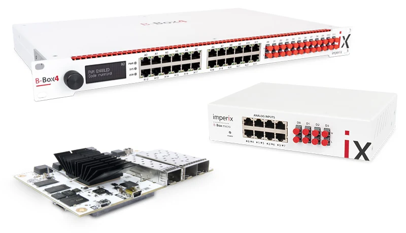
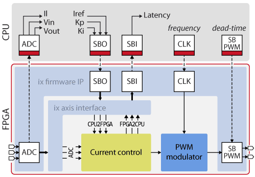
At the heart of every Imperix controller (B-Box RCP 3.0, B-Box 4, B-Board PRO) is a Xilinx FPGA that directly implements:
- PWM generation (all channels, with programmable dead-time)
- High-speed analog-to-digital conversion (ADC triggering and data capture)
- Digital I/O processing (encoder inputs, fault signals, GPIO)
- Protection signal path (comparator inputs → shutdown logic)
Because these functions run in dedicated hardware logic, they execute with:
- Zero dependency on CPU load or software state
- Nanosecond-level timing precision (not microsecond)
- Perfect multi-channel synchronization (±2.0 ns guaranteed)
Technical specifications (Imperix B-Box RCP 3.0):
- PWM resolution: 1.25 nanoseconds (800 MHz FPGA clock)
- PWM synchronization accuracy: ±2.0 ns across all channels
- Maximum control loop frequency: 500 kHz (2 μs loop period)
- ADC sampling: up to 1 MSPS per channel (synchronized with PWM)
This level of performance is impossible with timer peripherals in standard MCUs.
Deterministic Real-Time Scheduling (No Interrupt Jitter)
Imperix controllers use hardware-triggered execution instead of software interrupt schedulers. Control algorithms run in response to precise FPGA timing signals, not CPU interrupts.
What this means:
- Control loops execute at exactly the programmed interval (e.g., every 10.000 μs, not 10.002 μs)
- Sampling and actuation are tightly synchronized (zero phase lag uncertainty)
- Communication tasks (Ethernet, USB) do not steal control bandwidth
- Test results are 100% reproducible across power cycles and operating conditions
For researchers developing advanced control algorithms (model predictive control, adaptive control, sliding mode observers), this determinism is essential for validating theoretical predictions against experimental data.
Sub-Microsecond Protection Paths
Critical protection paths in Imperix controllers are implemented entirely in FPGA logic, with zero software involvement:
- Fault signal input (comparator output, desaturation detector)
- Threshold evaluation (within FPGA logic fabric)
- PWM shutdown command (direct hardware connection)
Response time: <1 microsecond from fault detection to PWM disable.
This hardware protection runs in parallel with control algorithms—they do not compete for resources. Even if the CPU is executing complex calculations, protection logic remains instantaneous.
Applications where this matters:
- SiC-based traction inverters (800V systems with <2 μs safe operating area)
- High-speed motor drives (100,000+ RPM with minimal bearing clearance)
- Grid-connected inverters (anti-islanding protection must meet IEEE 1547 timing)
- Research platforms testing experimental topologies (where failures are learning opportunities, not disasters)
Parallel Execution of Control and I/O (No Resource Contention)
Unlike sequential CPUs, FPGA logic operates as parallel hardware blocks. In an Imperix controller:
- PWM generation runs continuously in dedicated logic
- ADC sampling executes in parallel timing blocks
- Protection logic monitors faults independently
- Encoder interface decodes position in real-time hardware
- Control algorithm executes in DSP cores (ARM Cortex or Xilinx Zynq)
All simultaneously. No waiting. No shared resources.
This architecture naturally matches how power electronics converters operate—many things happening at once, all with precise timing relationships.
Why Determinism Matters: Real-World Performance Impact
Stable Current and Torque Control in Motor Drives
When ADC sampling, control computation, and PWM updates are aligned to nanosecond precision:
- Current control loops achieve 1-2 kHz bandwidth (vs. 500 Hz for jittery systems)
- Torque ripple in PMSM drives drops below 0.5% (vs. 2-3% with software control)
- Field-oriented control (FOC) tuning parameters remain valid across all operating speeds
- Sensorless control algorithms (phase-locked loop observers) track rotor position reliably
Application: A 250 kW EV traction inverter using Imperix control achieved 30% lower torque ripple compared to a commercial DSP-based controller, improving passenger comfort and reducing audible noise.
Reliable Over-Current Protection for High-Power Systems
Fast, deterministic protection allows engineers to:
- Push performance closer to device limits (extract maximum power density)
- Reduce conservative derating (smaller heatsinks, capacitors, inductors)
- Meet functional safety standards (ISO 26262 for automotive, IEC 61508 for industrial)
Application: A 1.2 MW grid-tied PV inverter used Imperix hardware protection to safely handle fault currents 3× nominal current without damaging SiC MOSFETs, avoiding costly warranty claims
Repeatable Behavior Across Operating Conditions
Determinism ensures that:
- Lab test results match field performance (no “works in simulation but not in hardware” surprises)
- Control behavior doesn’t depend on CPU load (enabling/disabling data logging doesn’t change dynamics)
- Production units behave identically (critical for automotive and aerospace certification)
For R&D teams and research labs, this repeatability is essential for credible experimentation and peer-reviewed publications.
Applications and Use Cases for Imperix FPGA Controllers
EV Traction Inverters and Motor Drives
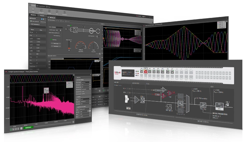
Imperix control development with MATLAB Simulink Imperix ACG SDK: Deploy Simulink models directly to FPGA hardware with automatic code generation
Imperix platforms excel in EV powertrains requiring:
- High-bandwidth current control (>2 kHz for torque response)
- Precise multi-phase PWM (6-phase motors, dual-motor configurations)
- Fast short-circuit protection (<1 μs for 400V/800V battery systems)
- Integration with battery management systems (CAN/LIN communication)
Supported control strategies:
- Field-oriented control (FOC) for PMSM and induction motors
- Direct torque control (DTC) with space vector modulation
- Sensorless control with sliding mode observers
- Active damping for LC filter resonances
Tools: MATLAB/Simulink blocksets enable model-based design with automatic code generation, accelerating development from concept to hardware validation.
Multi-Motor and Multi-Axis Drives
In robotics, aerospace actuators, and industrial automation with multiple synchronized motors:
- Coordinated control across 4-8 axes (deterministic timing prevents phase drift)
- Consistent PWM timing between drive stages (prevents beating and resonance)
- Scalable architecture (RealSync technology synchronizes multiple B-Box units to ±2 ns)
Application example: A 6-axis industrial robot used three Imperix B-Box RCP units (18 PWM channels total) with perfect synchronization, enabling trajectory tracking errors below 0.1 mm.
Grid-Connected Converters and Energy Storage
Grid-tied inverters for solar PV, wind turbines, and battery energy storage require:
- Precise current injection (THD % per IEEE standards)
- Fast grid fault response (low-voltage ride-through, anti-islanding detection)
- Stable phase-locked loop (PLL) behavior (grid synchronization under distorted voltage)
- Active/reactive power control (voltage support, frequency regulation)
Imperix advantages:
- Deterministic control loops prevent PLL instability during grid transients
- Hardware protection responds to over-voltage/under-voltage within 1 μs
- Supports complex topologies (T-type NPC, 3-level ANPC, modular multilevel converters)
Academic Research and Rapid Control Prototyping
For universities and R&D labs, Imperix provides:
- Transparent platform (full access to FPGA firmware via Xilinx Vivado)
- Flexibility for advanced control (implement custom algorithms in C/C++ or HDL)
- Safe testing environment (hardware protection prevents costly mistakes during experiments)
- Educational labs (B-Box Micro for undergraduate power electronics courses)
Notable institutions using Imperix:
- ETH Zurich (modular multilevel converter research)
- TU Delft (wind turbine emulation)
- University of Wisconsin-Madison (SiC device characterization)
- [Indian Institutes of Technology for EV and renewable energy research]
Imperix vs. Traditional Controllers: At-a-Glance Comparison
| Feature | DSP/MCU Controllers | Imperix FPGA Platforms |
|---|---|---|
| Execution Model | Interrupt-based, sequential | Parallel hardware logic |
| Timing Jitter | 1–10 µs | <10 ns |
| PWM Synchronization | Limited by timer peripherals | ±2.0 ns guaranteed |
| Protection Response | 5–50 µs (software-dependent) | <1 µs (hardware-implemented) |
| PWM Resolution | 10–50 ns (typical) | 1.25 ns (800 MHz clock) |
| Multi-Channel Sync | No guarantee across channels | Perfect sync (all channels) |
| Control Loop Frequency | Up to 50 kHz (typical) | Up to 500 kHz |
| Resource Contention | CPU shared across tasks | Dedicated hardware blocks |
| Reproducibility | Varies with CPU load | 100% repeatable |
| MATLAB/Simulink Integration | Limited | Native blockset support |
| FPGA Customization | Not available | Full Vivado access |
Conclusion: Determinism Is No Longer Optional—It's Required
As power electronics moves toward higher switching frequencies (100+ kHz), tighter control bandwidths (<10 μs loop periods), and increased power density (5+ kW/kg), real-time determinism has transitioned from “nice-to-have” to mission-critical requirement.
Timing jitter, delayed protection, and non-deterministic execution are no longer acceptable. They limit system performance, compromise safety, and create development headaches that slow time-to-market.
By architecting control platforms around FPGA-based parallel hardware rather than sequential software, Imperix delivers:
- Deterministic execution (±2 ns synchronization, zero jitter)
- Sub-microsecond protection (hardware fault response <1 μs)
- Nanosecond PWM precision (1.25 ns resolution, perfect multi-channel sync)
- Parallel processing (control and I/O execute simultaneously without resource contention)
This architecture provides reliable, repeatable, and high-performance control for:
- Electric vehicle traction inverters (ISO 26262 compliant)
- High-speed motor drives (>100,000 RPM with stable FOC)
- Grid-connected converters (IEEE 1547 and IEC 61850 compliant)
- Research platforms (academic institutions and R&D labs)
…while reducing development time, minimizing hardware risk, and enabling engineers to push performance boundaries safely.
Imperix in India: Local Support Through Pantronics India
mperix modular power hardware: plug-and-play building blocks for converter prototyping
In India, Pantronics India Pvt. Ltd. serves as the exclusive authorized distributor and development partner for Imperix power electronics solutions, providing:
Academic & Research Support
- Application engineering for IIT, NIT, and IISER research labs
- Custom training programs on FPGA-based power electronics control
- Educational pricing for universities and government-funded projects
- Collaborative research partnerships (EV traction, renewable energy, motor drives)
Industrial Solutions
- Turnkey rapid prototyping systems for automotive and industrial R&D
- Technical consultation for control algorithm development
- Local inventory for fast delivery (no long international shipping)
- On-site commissioning and troubleshooting support
Indian EV & Renewable Energy Focus
- Support for “Make in India” EV development programs
- Grid integration solutions for solar and wind projects
- Battery management system (BMS) development platforms
- ARAI automotive testing support (certification-ready prototypes)
Ready to Eliminate Timing Jitter in Your Next Power Electronics Project?
Whether you’re developing an EV traction inverter, designing a high-speed motor drive, or researching advanced grid-connected converters, Imperix FPGA controllers deliver the deterministic performance modern power electronics demands.
Frequently Asked Questions
Deterministic control ensures that sampling, computation, and PWM updates happen at exactly the same time in every control cycle. Even small timing variations (1-2 μs) can destabilize fast current loops, increase power losses, or delay fault response. Determinism delivers more stable, efficient, and safer operation in high-performance converters—especially those using SiC and GaN devices at 50+ kHz switching frequencies.
FPGAs generate PWM signals using dedicated hardware logic rather than software-controlled timer peripherals. This means PWM edges occur at precisely scheduled moments (±2 ns accuracy) with zero dependency on CPU load, interrupt latency, or cache behavior. Multi-channel synchronization is perfect across all phases, critical for multi-level converters and multi-motor drives.
PLCs and DSPs rely on sequential software execution and interrupts, which introduce latency and jitter. Imperix converts all time-sensitive control, PWM, and protection logic into parallel FPGA hardware, achieving deterministic execution and sub-microsecond response times.
Compared to dSPACE and OPAL-RT (also FPGA-based), Imperix offers:
- Lower cost for academic labs (price-competitive while maintaining performance)
- Native MATLAB/Simulink integration (similar workflow)
- Full FPGA customization access (Xilinx Vivado)
- Modular power hardware ecosystem (plug-and-play converter prototyping)
Absolutely. Imperix platforms are widely adopted in universities and research institutes for:
- Rapid control prototyping (test advanced algorithms on real hardware)
- Educational labs (B-Box Micro for undergraduate power electronics courses)
- PhD research (deterministic performance enables credible experimental validation)
- Conference publications (repeatable results critical for peer review)
The transparent architecture and MATLAB/Simulink integration make Imperix ideal for both teaching and cutting-edge research.
Protection logic is implemented directly in FPGA hardware, enabling <1 microsecond response from fault detection to PWM shutdown. This is 5-50× faster than software-based protection in DSP/MCU systems. Critical for protecting expensive SiC/GaN devices in high-voltage, high-current applications where every microsecond matters.
Yes. Imperix provides native Simulink blocksets (ACG SDK) that enable:
- Graphical programming (drag-and-drop control blocks)
- Automatic code generation (from Simulink model to FPGA hardware)
- Real-time simulation and parameter tuning
- Seamless workflow from simulation to hardware validation
This dramatically accelerates development time compared to hand-coding DSP firmware.
Imperix controllers support:
- Switching frequencies: Up to 500 kHz PWM (typical applications: 10-100 kHz)
- Control loop rates: Up to 500 kHz (2 μs loop period)
- Power ratings: From 1 kW (educational labs) to multi-MW systems (with modular power hardware)
The modular architecture scales from benchtop prototypes to full-scale industrial converters.
Yes. Imperix is purpose-built for rapid control prototyping, allowing engineers to:
- Validate control algorithms on real hardware with deterministic timing
- Test advanced strategies (MPC, neural network control, nonlinear observers)
- Reduce development time (no waiting for custom PCB fabrication)
- Lower risk of hardware damage (built-in protection logic)
Once validated, control code can be migrated to production hardware (or deployed directly using Imperix B-Board PRO for low-volume production).

Expert Technical Support
Need help building deterministic real-time control for EV traction inverters, motor drives, or grid-connected converters? We support Imperix FPGA users with PWM setup and nanosecond synchronization, fast protection logic (over-current/over-voltage/desaturation), high-speed ADC triggering aligned to PWM, encoder/resolver interfaces, multi-channel synchronization, and MATLAB/Simulink model deployment—so control timing, margins, and fault
response are validated before final hardware testing.
Mr. V. N Sudharsan (Technical specialist)
Mail ID: sudharsan@pantronicsindia.com