
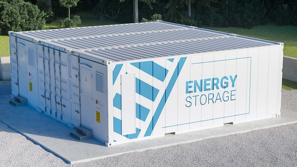
India’s battery storage market is moving from tenders to commissioning. India added 8.2 GWh of BESS in the first half of 2026, compared with 98.4 MWh in the same period of 2025. Every battery container sits behind a bidirectional power conversion system (PCS), and its power modules play a major role in efficiency, heat and ageing. This guide explains what damages them and how to select BESS power modules for India.
Quick answer:
BESS power module selection matters because the module affects conduction and switching losses, junction-temperature swings and overload capability in both charging and discharging. The right choice matches topology, voltage class, switching frequency and cooling to the duty cycle. Choosing on current rating or price alone can leave a module running hotter and ageing faster.
India’s BESS Market and Why It Raises the Bar for Power Modules
| Metric | Value | Basis |
|---|---|---|
| BESS added, H1 2026 | 8.2 GWh (vs 98.4 MWh in H1 2025) | ESS News |
| Operational BESS, Aug 2026 | 9.08 GWh | pv magazine India (Rubix Data Sciences) |
| Under construction / awarded / tendering | 79.92 / 24.13 / 63.53 GWh | Same source. This is a pipeline, not installed capacity. |
| Projected BESS requirement | 34.72 GWh (FY2026–27) → 236.22 GWh (FY2031–32) | Same source |
Figures vary with each source’s cut-off date. An earlier report put commissioned BESS at about 2.9 GW / 8.3 GWh as of June 2026 (EnergyWatts, JMK/IEEFA). Gujarat and Rajasthan account for nearly 88% of installed utility-scale BESS.
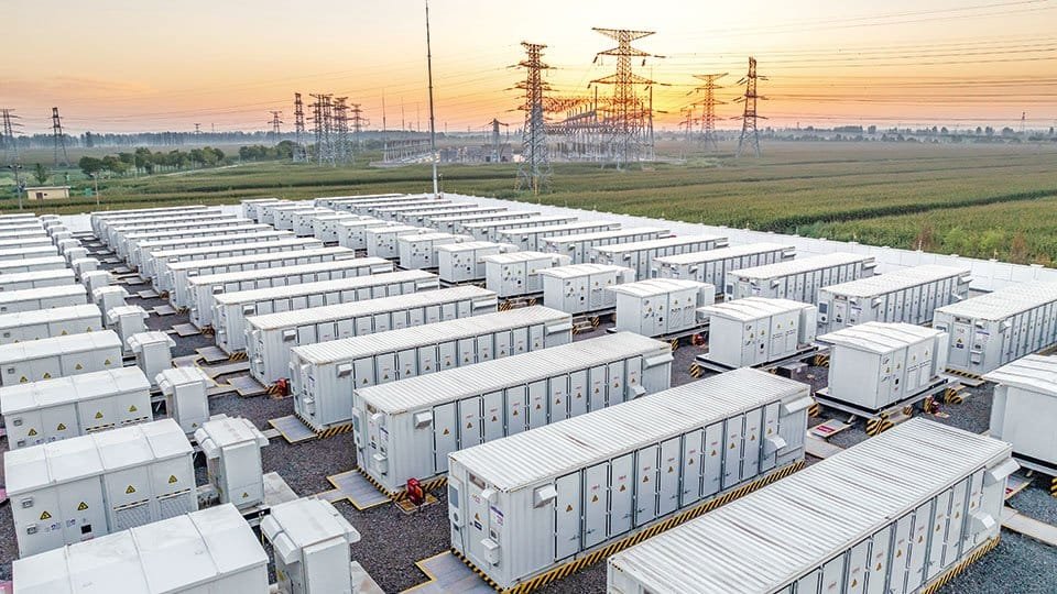
For module designers, this means frequent charge-discharge cycling, bidirectional operation and, in many projects, higher overload demands—often at sites with hot summers. Many sites are co-located with solar, so PCS and solar inverter stages often share topologies and module families.
What Causes Power Module Failures in BESS and Solar Inverters?
Direct answer:
The main concerns are thermal and power-cycling fatigue, sustained high junction temperature, electrical overstress and weak cooling. Gate-drive faults can add to the stress.
| Mechanism | What happens inside | Design response |
|---|---|---|
| Thermal / power cycling | Dispatch causes Tj swings. Different expansion rates strain bond-wire and solder interfaces; thermal resistance can rise. | Mission-profile life estimate, ΔTj limits, robust die-attach |
| Inversion vs rectification mode | Wear-out differs between the two modes and with power factor. | Check losses and Tj in both modes across the cos φ range |
| Overload (e.g. grid-forming duty) | Peak current can push Tj beyond the steady-state design point. | Current and thermal margin for the specified overload |
| Overvoltage | Stray inductance and DC-link transients can exceed blocking voltage. | Low-inductance layout, voltage headroom |
| Gate-drive faults | False turn-on or shoot-through increases stress. | Verified driver compatibility and protection |
| Cooling degradation | Dust, a degraded thermal interface or fan faults raise Tj. | Worst-case ambient design, maintainable heatsinks |
Aalborg University researchers report that semiconductors and capacitors contribute most to converter hardware failures, and that wear-out differs between inverting and rectifying modes. A wider IEEE Access review covers IGBT failure modes and lifetime testing. Still, not every failure starts in the module. PV inverter field reports in pv magazine also point to capacitors, fans and boards, so treat the module as one part of the reliability picture.
How Do Power Modules Affect BESS Efficiency?
Direct answer:
They determine conduction and switching losses. Those losses become heat, affecting cooling size and cycling stress.
- Topology: Vincotech says three-level topologies offer higher efficiency, lower harmonic distortion and lower EMI.
- SiC vs Si: Vincotech states that SiC reduces thermal stress at Si-level switching frequencies. It also describes up to two-thirds higher switching frequency at comparable Tj, with smaller filter inductors and more output from the same footprint.
- Packaging: Low parasitic inductance and a good thermal path matter alongside the chip.
These are manufacturer statements from the Vincotech BESS application page. Actual gains depend on the complete PCS design; no module alone guarantees efficiency or service life.
Direct answer:
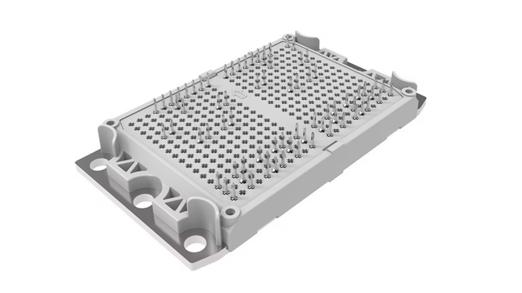
Vincotech lists modules for residential through central BESS, with silicon, hybrid and SiC options in low-inductance housings.
Examples from its product listing:
| Segment | Vincotech-stated features |
|---|---|
| Residential | Compact integrated design, H6.5 topology, optional integrated booster |
| Commercial & industrial | Three-phase 50–200 kW, optimised for 1000 V, IGBT H7, components rated for cos φ = +1 to −1 |
| Utility-string | 100–450+ kW, optimised for 1500 V, optional DC-DC optimisers, hybrid/full SiC, higher overload handling for grid-forming PCS |
| Central | Low-inductive VINco X housings, optimised for three-level designs, reduced passive components |
Two products worth exploring:
- flowNPC E3BP: Designs up to 250 kW, using 1200 V IGBT H7 with a SiC diode.
- flowANPC E3BP: 250+ kW designs, using 1200 V IGBT H7 with a SiC MOSFET.
Both quote a commutation loop of about 3–6 nH and a convex baseplate. The E3BP housing meets 2000 V system requirements. The benefits still depend on the complete design.
Define duty
Segment, power, DC voltage (1000 V or 1500 V), cycles per day, and whether the PCS is grid-following or grid-forming.
Check both operating modes
Evaluate losses in charge and discharge across the cos φ range.
Pick topology and frequency
Use the table above, then confirm with simulation.
Choose chip technology
Si IGBT, hybrid Si/SiC or SiC, weighed against efficiency target, filter size, cooling budget and cost.
Check voltage and current
Compare maximum DC-link voltage, including transients, with blocking voltage plus margin. In three-level designs each switch sees roughly half the DC link, a general principle. Check peak and overload current and duration.
Evaluate thermal performance
Calculate junction temperature at worst-case ambient with a partly dusty heatsink:
Then check ΔTj over the dispatch cycle. Conditions vary by site, so don’t assume one profile.
Confirm fit and protection
Housing, pinout, baseplate contact, gate-driver compatibility and short-circuit protection.
Simulate and verify
Use Vincotech’s VINcoSIM (see our PLECS guide), then confirm every figure and the product status in the datasheet.
Explore Vincotech Power Modules Through Pantronics India
Pantronics India lists Vincotech power modules for BESS, solar, drives, EV charging and UPS. For a broader introduction to module types, see the Power Modules guide. To help us understand your design, share:
- Segment and power level
- DC-link and grid voltage
- Topology and switching frequency
- Dispatch profile and overload requirement
- Ambient range and cooling method
- Volume and timeline
Parameter Glossary
PCS
Power conversion system between battery and grid
Tj / ΔTj
Junction temperature / its cycle swing
Rth(j-c)
Junction-to-case thermal resistance (K/W)
cos φ
Power factor; define leading/lagging reactive-power requirements separately
NPC / MNPC / ANPC
Neutral-point-clamped / modified (T-type) / active NPC
Choosing BESS power modules in India is a system decision. Match topology, chip technology and cooling to the duty cycle and site, then verify against the datasheet.
Explore Vincotech Power Modules Through Pantronics India
Pantronics India lists Vincotech power modules for BESS, solar, drives, EV charging and UPS. See all applications we support. When you contact us, share:
- Segment and power level
- DC-link and grid voltage
- Topology and switching frequency
- Dispatch profile and overload requirement
- Ambient range and cooling method
- Volume and timeline
Frequently Asked Questions (FAQ)
Power flows both ways and follows dispatch rather than sunlight. Check losses and Tj in charge and discharge, plus overload.
No. SiC can cut thermal stress or allow smaller inductors, but it costs more. Hybrid Si/SiC is another option.
Vincotech’s guidance is NPC/ANPC above 8 kHz, MNPC below 8 kHz, and flying capacitor where smaller inductors matter. Confirm by simulation.
Yes. Grid-forming PCS must supply higher short-term overload current, so check current rating, Tj peak and ΔTj at the specified overload and duration.
Sources don’t support that. Capacitors, fans and boards also fail.
Use the parameter list in the section below.

Need help selecting a BESS power module?
Talk to our technical team about topology, overload rating for grid-forming PCS, IGBT vs SiC and thermal margin across your dispatch cycle.
Mr. Vikrant Sharda (Power Module Expert)
Mail ID: v.sharda@pantronicsindia.com